
Computed Radiography (CR System) - 2
Image Readout
Exposed IP को reader unit में भेजा जाता है जहा इस IP से analog data प्राप्त होता है जिसे digital data में बदलने के लिए कंप्यूटर सिस्टम में भेजा जाता है | Reader unit, single or multiple plate configuration में उपलब्ध होती है |
 |
| CR imaging system |
एक typical cr reader unit के निम्न components होते है -
- Drive mechanism - to move the IP through the scanning process
- Optical system - includes laser, beam shaping optics, collecting optics and optical filters.
- Photo detector - e.g. Photomultiplier tube (PMT)
- Analog to digital converter (ADC).
Manufacturers की मशीन में अंतर cr reader unit में अंतर के कारण होता है | कुछ device में IP system move करता है तथा कुछ में optical components move करता है |
CR latent image की digitization में तीन महत्वपूर्ण चरण होते है -
Scanning
Scanning का purpose latent image को electrical signal (voltage) में बदलना होता है, जिसे बाद में digitized करके एक डिजिटल इमेज के रूप में प्रदर्शित किया जाता है | CR reader में सबसे पहले कैसेट से IP निकालकर drive mechanism में फिट किया जाता है | Drive mechanism cassette को एक समान गति से Y Axis पर move करवाता है, जिसे slow scan mode कहते है |
 |
| Scanning |
एक laser light source (He - Ne laser, 633 nm) से वाली red light को एक rotating तथा multifaceted mirror reflect करता है | यह red light, phosphor plate पर horizontal back and forth direction में deflect होती है तथा visible blue green light (390nm) release होती है | यह fast scan mode कहलाता है | Slow तथा fast scan mode CR computer द्वारा controlled किया जाता है | इस released light को fiber optic light guide के माध्यम से PMT या CCD के द्वारा collect किया जाता है | PMT इस visible light को collect, amplifies तथा rical signal में convert करती है | PMT के द्वारा output signal को एक ADC (analog to digital converter) के द्वारा digitized किया जाता है , जिससे digital image बनती है |
Sampling
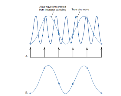
PMT से आने वाले digital signal को digitize करने से पहले इसे sample किया जाता है | ADC का एक महत्वपूर्ण performance characteristic sampling frequency होता है | Sampling से तात्पर्य है की एक एनालॉग सिग्नल को कितनी बार digitized form में बदला जाता है | Analog signal की sampling frequency बढ़ाने से digital data की pixel density बढ़ती है, जिससे डिजिटल इमेज की spatial resolution बढ़ती है |

Sample जितने एक दूसरे के पास पास होते है (increased sampling frequency) उतनी ही छोटी sampling pitch होती है | अर्थात sampling points के मध्य दुरी कम होती है | Sampling frequency बढ़ाने से sampling pitch घटती है जिससे pixel size भी घटती है | Manufacturers की CR equipment में अंतर IP की sampling process के कारण होता है |
कुछ निर्माता spatial frequency को maintain रखने के लिए sampling frequency को फिक्स रखते है तथा कुछ matrix size fix रखने के लिए sampling frequency में परिवर्तन करते है |
 |
| Fixed sampling frequency |
अगर spatial resolution नियत रखा जाता है तो image matrix size IP size के समानुपाती होता है | बड़ी IP में spatial resolution maintain करने के लिए बड़ी matrix size ली जाती है |

अगर matrix size को नियत रखकर IP size को परिवर्तित किया जाता है तो डिजिटल इमेज की spatial resolution प्रभावित होती है |
Quantification or pixel bit depth
यह इमेज के gray shade या contrast resolution को नियंत्रित करता है | Quantification process के दौरान प्रत्येक pixel एक brightness value को प्रदर्शित करता है जिसकी एक numerical value होती है | Quantification प्रत्येक recorded point की numerical value की शुद्धता (precision) को प्रदर्शित करता है | Pixel size तथा pitch spatial resolution को निर्धारित करते है तथा pixel bit depth, system की gray shades को प्रदर्शित करने की क्षमता को निर्धारित करता है | Pixel bit depth ADC के प्रकार तथा CR System manufacturer के द्वारा निर्धारित किया जाता है | जितनी ज्यादा pixel bit depth होती है उतनी ही ज्यादा digital image की contrast resolution होती है | e.g. 16 bit depth system has 216 pixel and 65536 gray shades.
Image source- Radiographic imaging and Exposure


कोई टिप्पणी नहीं:
एक टिप्पणी भेजें