Follow us to get latest updates

Digital Imaging लेबलों वाले संदेश दिखाए जा रहे हैं. सभी संदेश दिखाएं

Digital Imaging - 8 DR : Direct Detection DR System


Digital Radiography - 3

Direct Detection DR System

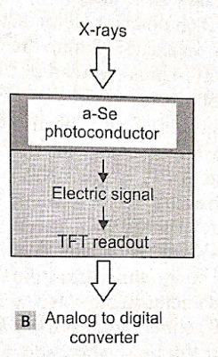
Direct Detection Flat Panel System में X-ray photoconductor material जैसे की amorphous selenium (a-Se) का उपयोग होता है, जो की x-rays को सीधे ही electron में बदल  देता है | 

Direct Detection Flat Panel System


        Direct Detection Flat Panel System  में indirect detection की तरह कोई भी scintillation material काम में नहीं लिया जाता है, जो की xrays को लाइट में परिवर्तित करता है |  इसमें क्योंकि selenium amorphous form में उपयोग में लिया जाता है इसलिए vapor deposit के द्वारा इसकी बड़ी प्लेट आसानी से बनायीं जा सकती है, जो की cost effective तथा reproducible technology है |  

DR Imaging System
DR Imaging System


         Selenium का atomic number (Z=34) थोड़ा सामान्य से कम होता है अतः इसकी thickness सापेक्ष रूप से थोड़ी ज्यादा ( लगभग 1mm) रखी जाती है |  इसकी x-ray detection property अच्छी होती है तथा इसकी spatial resolution भी अधिक होती है |  
     Selenium एक photoconductor होता है x-ray से एक्सपोज़ किया जाता है तो इसकी electrical conductivity परिवर्तित हो जाती है | यह altered electrical conductivity, x-ray intensity के समानुपाती होता है |  Selenium layer की दोनों सतहों के मध्य एक electrical field लगाया जाता है, जिससे produce electrons का thin film transistor (TFT) की  तरफ जाते समय lateral deffusion कम होता है | 
Analog to digital convertor for direct detection dr system


        जब इस डिटेक्टर को एक्सरे  द्वारा एक्सपोज़ किया जाता है तो selenium layer में electron emit होते है, जो की आरोपित वोल्टेज के कुछ भाग को डिस्चार्ज कर देते है |  यह वोल्टेज का डिस्चार्ज, रेडिएशन इंटेंसिटी के समानुपाती होता है, जिससे के letent charge image बनती है | यह चार्ज कैपेसिटर में संग्रहित कर लिया जाता है, तथा इस चार्ज पैटर्न को scan control line के द्वारा indirect detection system की तरह readout किया जाता है | अन्त में signal को image analysis के लिए digitized किया जाता है | 
        Selenium, humidity तथा temperature में परिवर्तन के प्रति अत्यधिक संवेदनशील (susceptible) होता है, अतः इसे environment से प्रोटेक्शन की आवश्यकता होती है |   

Source- Radiographic imaging and Exposure

source : Basic radiological physics Kappusamy Thayalan


Digital Imaging - 7 DR : Indirect Detection DR System


Digital Radiography - 2

Indirect Detection DR System

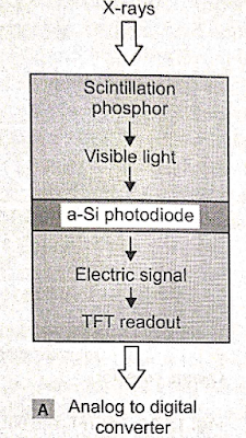
Indirct Detection Flat Pannel System में एक scintillation phosphor, amorphous silicon photo diode (a-Si) तथा flat TFT arrays होते है | इसमें CsI:Tl या Gd2O2S:Tb scintillation crystal काम में लिए जाते है |  ये scintillation crystal incident x-ray photon को light photon में परिवर्तित कर देते है |  इसका कार्य कैसेट में intensifying screen के समान  होता है | 

Phosphor Material
इसमें साधारणतया दो प्रकार के phosphor material काम में लिए जाते है |  
  • Terbium-dopped Gadolium Oxisulfide (Gd2O2S:Tb)
  • Thalium-dopped Cesium iodode (CsI:Tl)
Gd2O2S:Tb unstructured crystal produce करता है | यह phosphor screen-film technology से लिया गया है  |  इस system में scatter के द्वारा light का loss होता है जो की light photon के lateral spread के द्वारा होता है | जिससे लाइट फोटोन पास के pixel से क्रिया करता है | अतः इमेज की spatial resolution कम हो जाती है | 
CsI:Tl image intensifier technology के द्वारा लिया गया है | इसमें 5-10 µm चौड़ी तथा 600 µm लम्बी भिन्न भिन्न monoclinic needles होती है |  ये phosphor crystal hygroscopic (आद्रता ग्राही ) होते है तथा जल्दी degrade हो जाते है |  अतः इन्हे पूरी तरह से seal किया जाता है | इन crystal needles के कारण light forward direction ( सीधी दिशा ) में जाता है जिससे लाइट फोटोन का lateral spread कम होता है | इसमें फॉस्फर की मोटाई अधिक ली जा सकती है जिससे phosphor से x-ray photon का interaction अधिक होता है तथा quantum effeciency अधिक प्राप्त होती है | 
Detector का base glass substrate का बना होता है, जिसपर light sensitive a-Si, capacitor तथा TFT pixel के form में लगा होता है | इसके सबसे ऊपर का भाग scintillation phosphor होता है | 
Flat Pannel Array for dr system
Flat Pannel Array


a-Si तरल अवस्था में होता है जिसे paint के रूप में glass substrate पर फैला दिया जाता है | इस पूरी assembley को एक प्रोटेक्टिव आवरण के अंदर रखा जाता है जिसके बाहर cable connection के सॉकेट भी लगे होते है | 
Indirect Conversion DR System


TFT में तीन connection लगे होते है | 
  • Gate
  • Source
  • Drain
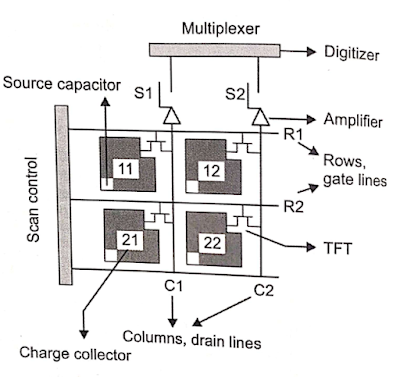
इसमें source एक capacotoe होता है |  Drain readout line (Vertical line) से जुड़ा होता है तथा Gate horizontal (rows) से जुड़ा होता है | TFT साधारणतया एक electronic switch होता है जिसे ON या OFF किया जा सकता है | जब gate के सिरों पर negative voltage लगाया जाता है तो TFT switch OFF अवस्था में होता है |  तथा अगर positive voltage apply किया  जाता है तो ON अवस्था में होता है | 
TFT Readout process
TFT Readout process


      सर्वप्रथम प्रत्येक detector element के capacitor जो charge को स्टोर करता को earthed कर दिया जाता है, जिससे की residual charge भूमि में चला जाता है |अब इसे X-rays से एक्सपोज़ किया जाता है तो scintillation crystal visible light उत्सर्जित करता है | ये द्रश्य प्रकाश photo-diode (a-Si) को एक्सपोज़ करता है | जिससे फोटो डायोड से इलेक्ट्रान निकलते है | जिससे प्रत्येक डिटेक्टर एलिमेंट में चार्ज बनता है | इस चार्ज को कैपेसिटर में स्टोर कर लिया जाता है | बाद में प्रत्येक डिटेक्टर एलिमेंट में चार्ज को readout किया जाता है | 
Flat-panel digital detector fixed in a modified x-ray table
Flat-panel digital detector fixed in a modified x-ray table  


        X-ray  exposure के दौरान gate पर negative voltage appply करके सभी transistor को OFF position में रखा जाता है | प्रत्येक detector element में उत्पन्न charge capacitor में store हो जाता है |  Readout process के दौरान gate पर positive voltage इस प्रकार आरोपित किया जाता है की एक बार में एक row gate ON condition में हो | यह स्विच S1, S2 से होते हुए vertical wire c1,c2 के द्वारा digitizer से जुड़े होते है | Multiplexer sequence के रूप में एक बार में एक column select करता है | प्राप्त चार्ज को amplify किया जाता है तथा digitizer को स्थानांतरित कर दिया जाता है | 
Analog to Digital Converter for Indirect Conversion


        अतः प्रत्येक detector element में gate, row को सेलेक्ट करता है तथा multiplexer कॉलम को सेलेक्ट करता है | इस प्रकार प्रत्येक डिटेक्टर एलिमेंट में चार्ज को readout कर लिया जाता है तथा सिगनल को डिजिटाइज़ करके इमेज एनालिसिस के लिए स्टोर किया जाता है | 

Source- Radiographic imaging and Exposure

source : Basic radiological physics Kappusamy Thayalan


Digital Imaging - 6 DR : Introduction


Digital Radiography - 1

Digital Image receptors (DR IRs) में एक self scanning readout mechanism होता है, जिसे एक X-ray detector के array पर आरोपित किया जाता है | ये patient से आने वाले exit radiation को प्राप्त करता है तथा X-ray की varying intensity (परिवर्तनीय तीव्रता ) को उसी अनुपात में digitization के elecलिए tronic signal में परिवर्तित करता है | 

DR imaging system


        CR system में एक two step image acquisition process होता है जिस कारण image capture तथा image readout में बहुत बड़ा समयांतराल होता है |  DR imaging system में इन दोनों प्रक्रिया को एक साथ combine कर दिया जाता है | फलस्वरूप DR image exposure के तुरंत बाद प्राप्त हो जाती है | DR image receptor, CR image receptor की तुलना में ज्यादा fragile तथा ज्यादा expensive होते है  | Direct radiography के लिए कई प्रकार के IRs काम में लिए जाते है |  जो की निम्न है -

Indirect detection Flat Pannel System.........Read more.
Direct detection Flat Pannel System ........Read more.

Source- Radiographic imaging and Exposure


Digital Imaging - 5 CR : Image Readout


Computed Radiography (CR System) - 2

Image Readout

Exposed IP को reader unit में भेजा जाता है जहा इस IP से analog data प्राप्त होता है जिसे digital data में बदलने के लिए कंप्यूटर सिस्टम में भेजा जाता है | Reader unit, single or multiple plate configuration में उपलब्ध होती है | 

CR imaging system
CR imaging system


एक typical cr reader unit के निम्न components होते है -

  1. Drive mechanism - to move the IP through the scanning process
  2. Optical system - includes laser, beam shaping optics, collecting optics and optical filters.
  3. Photo detector - e.g. Photomultiplier tube (PMT)
  4. Analog to digital converter (ADC).

Manufacturers की मशीन में अंतर cr reader unit में अंतर के कारण होता है | कुछ device में IP system move करता है तथा कुछ में optical components move करता है | 

CR latent image की digitization में तीन महत्वपूर्ण  चरण होते है -

Scanning

Scanning का purpose latent image को electrical signal (voltage) में बदलना होता है, जिसे बाद में digitized करके एक डिजिटल इमेज के रूप में प्रदर्शित किया जाता है  | CR reader में सबसे पहले कैसेट से IP निकालकर drive mechanism में फिट किया जाता है | Drive mechanism cassette को एक समान  गति से Y Axis पर move करवाता है, जिसे slow scan mode कहते है | 

cr imaging system scanning
Scanning


एक laser light source (He - Ne laser, 633 nm) से वाली red light को एक rotating तथा multifaceted mirror reflect करता है | यह red light, phosphor plate पर horizontal back and forth direction में deflect होती है तथा visible blue green light (390nm) release होती है | यह fast scan mode कहलाता है | Slow तथा fast scan mode CR computer द्वारा controlled किया जाता है | इस released light को fiber optic light guide के माध्यम से PMT  या CCD के द्वारा collect किया जाता है | PMT इस  visible light को collect, amplifies तथा rical signal में convert करती है | PMT के द्वारा output signal को एक ADC (analog to digital converter)  के द्वारा digitized किया जाता है , जिससे digital image बनती है |  

Sampling

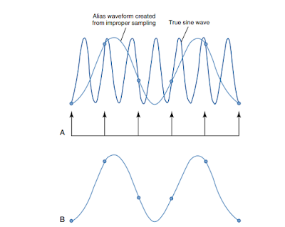
PMT से आने वाले digital signal को digitize करने से पहले इसे sample किया जाता है  | ADC का एक महत्वपूर्ण performance characteristic sampling frequency होता है | Sampling से तात्पर्य है की एक एनालॉग सिग्नल को कितनी बार digitized form में बदला जाता है | Analog signal की sampling frequency बढ़ाने से digital data की pixel density बढ़ती है, जिससे डिजिटल इमेज की spatial resolution बढ़ती है | 

cr system sampling


Sample  जितने एक दूसरे के पास पास होते है (increased sampling frequency)  उतनी ही  छोटी sampling pitch होती है | अर्थात sampling points के मध्य दुरी कम होती है | Sampling frequency बढ़ाने से sampling pitch घटती है जिससे pixel size भी घटती है | Manufacturers की CR equipment में अंतर IP की sampling process के कारण होता है | 


कुछ निर्माता spatial frequency को maintain रखने के लिए sampling frequency को फिक्स रखते है तथा कुछ matrix size fix रखने के लिए sampling frequency में परिवर्तन करते है |  

Fixed sampling frequency


अगर spatial resolution नियत रखा जाता है तो image matrix size IP size के समानुपाती होता है | बड़ी IP में spatial resolution maintain करने के लिए बड़ी matrix size ली जाती है | 

Fixed matrix size


अगर matrix size को नियत रखकर IP size को परिवर्तित किया जाता है तो डिजिटल इमेज की spatial resolution प्रभावित होती है | 

Quantification or pixel bit depth

यह इमेज के gray shade या contrast resolution को नियंत्रित करता है | Quantification process के दौरान प्रत्येक pixel एक brightness value को प्रदर्शित करता है जिसकी एक numerical value होती है | Quantification प्रत्येक recorded point की numerical value की शुद्धता (precision) को प्रदर्शित करता है | Pixel size तथा pitch spatial resolution को निर्धारित करते है तथा pixel bit depth, system की gray shades को प्रदर्शित करने की क्षमता को निर्धारित करता है | Pixel bit depth ADC के प्रकार तथा CR System manufacturer के द्वारा निर्धारित किया जाता है |  जितनी ज्यादा pixel bit depth होती है उतनी ही ज्यादा digital image की contrast resolution होती है |  e.g. 16 bit depth system has 216 pixel and 65536 gray shades.

Image source- Radiographic imaging and Exposure


Digital Imaging - 4 CR : Image Capture


Computed Radiography (CR System) - 1

Computed Radiography Image Receptors (CR IRs) को portable या table और upright X-ray unit पर fix करके  बनाया जाता है | CR IR में एक कैसेट होती है, जिसमे एक imaging plate (IP) लगी होती है | इस IP पर एक phosphor लगा होता है जो पेशेंट को पार करके आने वाले रेडिएशन से क्रिया करता है | Phosphor के द्वारा अवशोषित ऊर्जा का कुछ भाग द्रश्य प्रकाश के रूप में उत्सर्जित हो जाता है (Luminescence) तथा बाकि ऊर्जा latent image के रूप में phosphor में  store हो जाती है | 

computed radiography system


Image receptor (IR)  मुख्यतया Support, phosphor तथा protective layer की बनी होती है | इसमे मुख्य phosphor barium fluorohalide crystal होते है जिन्हे europium के साथ dopped किया जाता है | [ BaFBr (85%) and BaFI (15%) : Eu] यहाँ europium activator कहलाता है, यह बहुत ही कम मात्रा में मिलाया जाता है,  यह phosphor की photostimulable luminescence (PSL) property  के लिए उत्तरदायी होता है |       CR imaging system में image acquisition के दो चरण होते है : 

 1. IP में image capture करना 

 2. Image readout

Image capture in IP 

जब पेशेंट से exit radiation cassette पर गिरता है तो फॉस्फर के द्वारा रेडिएशन अवशोषित होने के कारण latent image का निर्माण होता है | Activator crystal ,में defects उत्पन्न कर देता है जिसे F-center कहते है | ये F-center electron trap कर सकते है | इस प्रक्रिया में सबसे पहले रेडिएशन से ऊर्जा अवशोषित करके फोटोइलेक्ट्रिक प्रभाव के कारण europium atom का आयनन होता है तथा valence band में एक इलेक्ट्रान उत्सर्जित होता  है | 

X-rays + Eu+2 = Eu+3 + e-

ये इलेक्ट्रान valence band से conduction band में चले जाते है जहा से ये forbidden zone के F-center में trap हो जाते है | इन F-center पर इलेक्ट्रान  समय तक रह सकते है  | अतः एक एक्सपोज़र में करोडो इलेक्ट्रान F-center में trap हो जाते है |  इन इलेक्ट्रॉन्स की संख्या अवशोषित रेडिएशन एनर्जी  समानुपाती होती है | 

लम्बे समय में ये trapped electron अपने आप  ग्राउंड स्टेट आ जाते है | लेकिन फॉस्फर को एक red light souce के द्वारा एक्सपोज़  करके भी इन  इलेक्ट्रान की ग्राउंड स्टेट में वापस आने  प्रक्रिया को बढ़ाया जा सकता है | इसी कारण इसे photo stimulable phosphor कहते है | 

computed radiography latent image formation


जब imaging plate को एक red laser light के द्वारा एक्सपोज़ किया जाता है तो F-center energy absorb करता है तथा उसे इलेक्ट्रान को दे देता है | इलेक्ट्रान conduction band में पहुंच जाता है जहा से वह valence band में पहुंच जाता है तथा blue green light उत्सर्जित करता है जिसकी ऊर्जा red laser light से ज्यादा होती है | इलेक्ट्रान Eu+3 से  जुड़ कर Eu+2 बनाता है | 

फॉस्फर से सभी trapped electron release नहीं हो पाते है इसलिए IP को एक बहुत bright light source के द्वारा एक्सपोज़ किया जाता है जिससे सबसे trapped electron release हो जाते है | अब IP को दुबारा रेडिएशन एक्सपोज़र के लिए काम में लाया जा सकता है | 

Imaging Plate 

Phosphor  को एक flexible screen (0.5 mm)  के रूप में बनाया जा सकता है जो एक द्रढ़ कैसेट में बंद रहती है जिसे imaging plate (IP)  कहते है | सबसे पहले imaging plate Fuji, japan के द्वारा सन 1983 में बनायीं गयी जो screen-film cassette के समान होती है | Cassette अलग अलग साइज में उपलब्ध होती है जिनमे 14"X17", 14" X 14", 10" X 10" तथा 8" X 10" मुख्य है | यह अलग अलग वैरायटी जैसे general radiography, mammography, dental radiography आदि के लिए भी उपलब्ध होती है | General radiography के लिए spatial frequency 2-3 lp/mm तथा mammography के लिए 10 lp/mm होती है | 


Image source- Radiographic imaging and Exposure


Digital Imaging - 3 DR : Modulation Transfer Function


Modulation Transfer Function (MTF)

Body tissue को पार करने वाले रेडिएशन की इंटेंसिटी में अंतर होने  कारण radiographic image brightness level (Grayscale) की एक रेंज प्रदर्शित  है | कोई भी anatomic detail तब सबसे अच्छी प्रदर्शित होती है जब object के ब्राइटनेस लेवल तथा उसके पास के टिश्यू के ब्राइटनेस लेवल में अंतर (high contrast) हो | 


बड़ी साइज के ऑब्जेक्ट (Low spatial frequency object) को ज्यादा आसानी से देखा जा सकता है | जैसे जैसे ऑब्जेक्ट की साइज कम होती जाती है इसकी spatial frequency बढ़ती जाती है अतः इसे देखा जाना ज्यादा कठिन होता जाता है | 

Modulation transfer function (MTF) किसी imaging system की किन्ही अलग अलग साइज के anatomic object के contrast को प्रदर्शित करने की क्षमता होती है | 

इसकी मान 0 (no diffrence in brightness level) तथा 1.0 (maximum diffrence in brightness level) के मध्य होता है |  

MTF = (Maximum intensity-Minimum intensity) / (Maximum intensity + Minimum intensity)

MTF=1

यहाँ maximum तथा minimum brightness में अंतर अधिकतम (100% diffrence ) होता है | Larger object (low spatial frequency) के साथ MTF = 1 आसानी से प्राप्त किया जा सकता है | 

MTF= 0

यहाँ maximum तथा minimum brightness में अंतर नहीं होता है | Smaller object (High spatial frequency) को प्रदर्शित किया जाना कठिन होता है |  

अतः अधिकांश digital imaging system की MTF value 1.0 से कम होती है | 

Image source- Radiographic imaging and Exposure


Digital imaging - 2 DR : Spatial Frequency & Resolution


Digital Image Characteristics - 2

Spatial Frequency and Spatial Resolution

किसी imaging system की small oblects को resolve (विभेद) करने की क्षमता के अध्ययन के लिए spatial frequency तथा इसका spatial resolution के साथ सम्बन्ध को समझना आयश्यक है | 

Digital Imaging में spatial resolution मुख्यतया pixel  की size से सम्बंधित होती है | Anatomic detail छोटे तथा बड़े object से बनी होती है | रेडियोग्राफिक इमेज इन detail को white and black brightness level में अंतर के रूप में बताती है | 

Small object की higher spatial frequency तथा large object की lower spatial frequency होती है | Small object (higher spatial frequency) की imaging, large object (lower spatial frequency) से ज्यादा कठिन होती है | 

Spatial Frequency को line pair per millimeter (lp/mm) में मापा जाता है | इसे रिकॉर्ड करने के लिए एक डिवाइस काम में ली जाती है जिसे resolution test pattern कहते है | 

resolution test pattern


कोई imaging system जो ज्यादा lp/mm (higher spatial frequency) को resolve कर सकता है की ज्यादा spatial resolution होती है | 

spatial resolution and spatial frequency


किसी imaging system की किसी विशेष spatial frequency को विभेद करने की क्षमता इसकी pixel size से प्रभावित होती है | 

Image source- Radiographic imaging and Exposure


Digital Imaging- 1 DR : Pixel, Pixel Bit Depth, Pixel Density & Pitch


Digital Image Characteristics

रेडियोग्राफिक इमेजिंग के दौरान पेशेंट से होकर निकलने वाला radiation में anatomic tissue से x-rays के transmission तथा absorption के कारण x-ray intensities में बहुत ज्यादा  परिवर्तन आ  है  | Image receptor इस exit radiation प्राप्त करता है तथा एक latent image या invisible image बनाता है | 

Digital Imaging में latent image एक digital data के रूप में store की जाती है तथा display monitor पर देखने हेतु computer के द्वारा process की जाती है  | इसमें एक specialized imgae receptor होता है जो computerized radiographic image उत्पन्न करता है  | वर्तमान में दो तरह के Digital radiographic system उपलब्ध है जो की Computed Radiography (CR) तथा Direct Radiography (DR) system है |  दोनों ही imaging system में कंप्यूटर के द्वारा कंप्यूटर के द्वारा रेडियोग्राफिक इमेज को बहुत सारे तरीको से manupulate किया जा सकता है |  

Digital Image numerical data से बनी होती है जिसे  कंप्यूटर के द्वारा manupulate किया जा सकता है |  इसमें कंप्यूटर के द्वारा इसके contrast तथा brightness में बहुत ज्यादा परिवर्तन किया जा सकता है | 

Pixel

Digital image को Matrix के रूप में रिकॉर्ड किया जाता है | यह matrix rows तथा columns के combination से बनती है जिससे square shape के picture element बनते है जिन्हे Pixel कहते है  | Pixel की साइज को माइक्रोन  है  | 

100 micron = 0.1mm

यहाँ प्रत्येक पिक्सेल की एक numerical value होती है जिसे display monitor पर एक single brightness level के रूप में प्रदर्शित किया जाता है  | Image matrix में pixel की location patient या volume tissue में एरिया के संगत (correspond) होती है | 

एक दिए गए anatomic area या FOV (Field of View) में अलग-अलग matrix में निम्न pixel होते है | 

Matrix Size No of Pixel
1024X1024 1048576
2048X2048 4194304

बड़े matrix size तथा छोटे pixel की बहुत अधिक संख्या लेने पर इमेज क्वालिटी सुधरती है लकिन इसके साथ ही computer processing time, network transmission time तथा digital storage space भी बढ़ते है |  
pixel matrix size
All image have fix FOV, Image A- Matrix size 64X64, Image B- Matrix size 215X215, Image C- matrix size 2048X2048


Pixel Size = FOV/Matrix Size
यहाँ एक fixed matrix size के लिए FOV  बढ़ता है तो pixel size भी बढ़ता है | (Direct Relation)
अगर एक fixed FOV के लिए Matrix size बढ़ता है तो pixel size घटता है |  (Inverse relation) 

Pxel Bit Depth

प्रत्येक पिक्सेल की numerical value tissue से पास होकर जाने वाले x-ray radiaiton के relative attenuatuin पर निर्भर करती है | Bone tissue जहा ज्यादा xray attenuate होती है के लिए pixel की numerical value कम होती है, तथा सॉफ्ट टिश्यू के लिए pixel के लिए numerical value ज्यादा होती है |  
Binary digits
कंप्यूटर Binary numbers ( 0 and 1) के द्वारा operate तथा communicate करते है | यह binary number 0 तथा 1 का कॉम्बिनेशन होती है | ये 0 तथा 1 bit कहलाते है | ये कंप्यूटर की इनफार्मेशन की बेसिक यूनिट कहलाते है 
8 bit = 1byte
Binary number का उपयोग डिजिटल इमेज के ब्राइटनेस लेवल (grayscale) को प्रदर्शित करने में होता है | 
प्रत्येक पिक्सेल की Pixel Bit Depth या number of bits होती है यह analog signal के digital signal में digitizing में precision (शुद्धता ) की मात्रा को  करता है | जिसके द्वारा डिजिटल इमेज में प्रदर्शित करने के लिए gray shade प्राप्त होते है | 
Radiographic pixel


Bit depth एक  anlog to digital converter के द्वारा निर्धारित होती है | यह किसी भी digital imaging system का एक आवश्यक भाग होता है | 
Bit depth को 2 की घात n के द्वारा प्रदर्शित किया जाता है | यहाँ 2 binary number के कारन उपयोग में लिया जाता है | अतः bit depth निम्न सूत्र के द्वारा प्रदर्शित की जाती है -
No of bits = 2n
यहाँ n bit depth है | 

Bit DepthNo of bitsNo of Shades
12 2124096
14 21416384
1621665536

एक सिस्टम जितने gray shades को digitize तथा डिस्प्ले करता है, उतना ही उसमे contrast resolution अधिक होता है | जिससे image उतना ही अधिक anatomic detail को प्रदर्शित करती है तथा small anatomic area में विभेद उत्पन्न कर सकती है | 

Pixel Density

किसी image के per unit area में उपस्थित pixel की संख्या pixel density कहलाती है | Pixel density बढ़ने पर spatial resolution बढ़ती है | 

Pixel Pitch

Pixel pitch


दो pixel के  केन्द्र के मध्य दुरी pixel pitch कहलाती है | छोटे साइज के पिक्सेल में Pixel Pitch कम होती है जिससे spatial resolution बढ़ती है | 
Image source- Radiographic imaging and Exposure