Follow us to get latest updates

FLUOROSCOPY लेबलों वाले संदेश दिखाए जा रहे हैं. सभी संदेश दिखाएं

FLUOROSCOPY PERFORMANCE - ABC


AUTOMATIC BRIGHTNESS CONTROL

यह Fluoroscopy का एक फंक्शन होता है, जो कि kVp, mA या दोनों को automatically adjust करके fluoroscopic image की ओवरऑल performance को कंट्रोल करता है | इसके द्वारा मॉनिटर पर इमेज ब्राइटनेस को नियत रखा जाता है | यह एक feed back circuit होता है, जोकि आउटपुट स्क्रीन की लाइट इंटेंसिटी या वीडियो कैमरा सिग्नल का मापन करता है | 
FLUOROSCOPY PERFORMANCE - ABC

Image intensifier tube की light output को मॉनिटर करने के लिए एक फोटोमल्टीप्लायर ट्यूब या एक फोटोकैथोड काम में लिया जाता है | इसके संगत ब्राइटनेस में परिवर्तन होने पर उसे जनरेटर तक एडजस्टमेंट के लिए भेजा जाता है | Generator exposure rate को kVp, mA या दोनों को चेंज करके नियंत्रित करता है | इस एडजस्टमेंट के लिए output screen  के central area की ब्राइटनेस को  मापा जाता है | 
ब्राइटनेस को kVp, mA दोनों से एडजस्ट किया जा सकता है, जो कि contrast तथा parient dose दोनों पर प्रभाव डालती है | एडजस्टमेंट के तीन तरीके निम्न अनुसार होते हैं -
  • Change of kV at constant mA
  • Change of mA at constant kV
  • Change of both kV and mA

जब II tube की patient केthin part से thick part की और गति करती है तो kV बढ़ने से patient dose तथा contrast कम प्राप्त होता है |  इसके अलावा जब mA बढ़ाया जाता है तो contrast अच्छा प्राप्त होता है तथा patient dose भी अधिक प्राप्त होता है |  
FLUOROSCOPY PERFORMANCE - ABC

सामान्यतया II tube की input dose rate को एडजस्ट करने के लिए सबसे पहले mA एडजस्ट किया जाता है | mA के अपनी अधिकतम सीमा तक पहुंचने पर input dose rate करने के लिए kV को एडजस्ट किया जाता है | 


FLUOROSCOPY PERFORMANCE


Image intensifier tube की performance, Image की illumination (चमक ) बढ़ने से बढ़ती है | यह output phosphor पर light photon के multiplication होने तथा image minification से होता है | Illumination का बढ़ना tube के brightness gain पर निर्भर करता है |  अतः brightness gain तथा conversion factor term को इमेज इंटेंसिफायर ट्यूब के परफॉर्मेंस के आकलन के लिए काम में लिया जाता है |
FLUOROSCOPY PERFORMANCE

Brightness gain

Brightness gain, output phosphor तथा input phosphor पर brightness का अनुपात होता है | यह दो कारको पर निर्भर करता है |
Brightness gain =  Flux gain X Minification Gain 

Flux Gain

Photocathode तथा anode के मध्य उच्च विभांतर के कारण electron anode की तरफ त्वरित होते हैं | जिससे output phosphor पर light intensity बढ़ती है | Output screen light photon तथा input screen x-ray photon के अनुपात को Flux Gain कहते हैं | इसका मान 50 के लगभग होता है |

Flux Gain = Number of Output Light Photon / Number of Input X-ray Photons

Minification Gain

Input phosphor image की तुलना में output phosphor image की size कम होने पर light Intensity बढ़ती है | इसे minification gain कहते है | यह input तथा output screen के size के अनुपात के वर्ग के बराबर होता है | 
प्रश्न : यदि किसी II Tube के लिए d1 तथा d2 क्रमशः 300mm तथा 30mm तथा II Tube का Flux gain 50 हो तो Brightness gainहोगा | 
उत्तर :  
                                Flux Gain = 50
                                Minification gain = (d1/d2)2
                                                           = (300/30)2
                                                           = 100
                                 Brightness Gain = Flux gain X Minification gain
                                                           = 50 X 100
                                                           = 5000
Brightness gain एक मापने योग्य quantity नहीं होती है | अतः किसी II Tube की performance को ज्ञात करने के लिए conversion factor term काम में ली जाती है |
fluoroscopy performance

Conversion Factor

यह output phosphor की brightness (luminance, CD/m2) तथा input x-ray exposure rate (𝛍Gy/sec) का अनुपात होता है | इसकी वैल्यू brightenss gain के 1% के बराबर होती है | इसकी typical range 50-300 (CD/m2)/(𝛍Gy/sec)होती है, तथा इसकी संगत brightness gain range 5000-30000 होती है |  किसी II tube की जितनी अधिक अधिक brightness gain तथा conversion factor होता है, उसकी उतनी अधिक efficiency होती है | 


Fluoroscopy

Fluoroscopy is an imaging technique in which a live xray image of the patient's internal structure can be taken and viewed. Image Intensifier Fluoroscopy replaced Direct vision fluoroscopy due to the many limitations of Direct vision fluoroscopy. Image Intensifier (II) fluoroscopy is a modern system, consisting of an Image Intensifier and closed circuit TV system. Hence, it is also called IITV.
Fluoroscopy image should have maximum image detail, which requires more image brightness. Image intensifier has higher image brightness, which makes this image detail more visible. Image brightness depends on anatomy, mA and kVp. Hence image brightness can be changed in fluoroscopy by controlling mA and kVp.
A Fluoroscopy examination lasts for several minutes, which als
Fluoroscopy
o increases the radiation dose of the patient. The exposure rate is kept as low as 200 mR / Min to reduce the radiation dose of the patient. Fluoroscopy systems have low current output that ranges from 1 to 5 mA and produces 30 images per second. Whereas the current output in radiographic exposure ranges from 100 to 200 mA which is much higher than the fluoroscopic current output. In Fluoroscopy, few X-ray photons are taken to create a single fluoroscopic image. Therefore, comparing the number of X-ray photons, the fluoroscopic image is inferior to the radiographic image.
A special feature of a fluoroscopy machine is the Deadman switch. Continuous xray beam is achieved by continuously pressing either the hand switch or the foot pedal. The exposure is terminated by releasing the pressure applied on the pedal or switch.
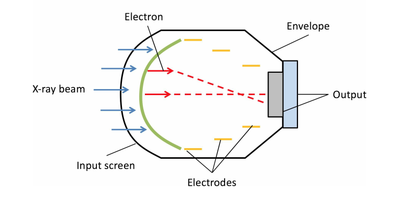
Image intensifier tube converts exit radiation from the patient into visible radiation. The image intensifier consists of an evacuated glass envelope. The surface of the patient side of this vacuum bottle is called aluminum. It is made of 1 millimeter aluminum.
This surface is made curved to reduce the resistance of air pressure. Due to the evacuated glass envelope, its size is limited and its diameter range is 23 to 57 centimeters. Glass envelope is kept in a metal container to prevent rough handling and damage.
Image intensifier has four parts -

  1. Input screen
  2. Focusing electrodes
  3. Anode
  4. Output phosphor

Input screen


It is inside the aluminum window. It is made up of three layers.
II Input Window
This is a convex substrate layer, which is generally made of aluminum or Titanium-like metal with low atomic number. Its thickness is about 0.5mm. This allows the x-ray beam to come into the image intensifier tube with minimal attenuation. In addition, it provides protection to the sensitive input components of the tube and maintains the vacuum in the tube.
Input Phosphor has a thickness of 200 to 400 microns. Sodium activated caesium iodide is used as input phosphor. Its xray absorption efficiency is 70 to 90%. Caesium iodide crystal has a special property. Its crystals, whose diameter is 5 micrometers, are very tightly packed as a vertical needle, and send the light towards the output screen in a forward direction, like a fiber optic, allowing the lateral of the light. The spread is also less. Caesium iodide crystal produces about 3000 light photons of the blue light spectrum from an x-ray photon.
Photocathode
Light photons resulting from photocathode input phosphor fall on the photocathode. The photocathode is made of a very thin layer of Antimony caesium (SbCs3). The photocathode input is coated on the inside surface of the phosphor. It converts a visible light into an electron. Antimony caesium (SbCs3) absorbs blue light. That is, it has spectral matching to the blue light emitted from Caesium iodide. Photocathode emits 200 electrons per X-ray photon.
The input screen is placed at a higher negative potential than the anode, so that electrons move faster towards the anode. The input screen has a diameter of 150 to 400 millimeters depending on the clinical application.

Focusing Electrodes

Input screen is placed at negative potential relative to anode. There are D1, D2 and D3 electrodes between the input screen and the anode. These are usually metal rings placed at a positive voltage relative to the photocathode. These electrodes accelerate the electron and focus the output screen. The length of the image intensifier tube is about 50 centimeters and there is a voltage difference of 25000 volts between the photocathode and the anode.

Electrons come to the anode carrying images of input phosphors with high velocity and energy. Therefore, the electrons receive energy and form a minified, inverted image on the output phosphor. Due to the curved nature of image intensifier, electron foxing is promoted, but this produces pincushion distortion.

Anode

It is a circular plate between which there is a hole. Through this hole, electrons reach the output phase. It is made by coating 2 mm of aluminum on the output phosphor inside surface. It is electric conductive and its potential difference is 25kV more than the input screen. It works for receiving accelerated ekectrons.

Output screen

Silver dopped zinc cadmium sulfide crystal (ZnCdS: Ag) is used as output phosphor. It is dopped on the inside surface of the output window. Its diameter is 25 to 35 mm and phosphor thickness is 4-8 mm. It absorbs electrons and emits large amounts of green light. In this green light, the video camera is the most sensitive. Each electron produces about 1000 light photons.

Image Intensifier Fluoroscopy


Fluoroscopy एक imaging technique है जिसमें patient के internal structure की live xray image ली तथा देखी जाती  है | Technology के आधार पर फ्लोरोस्कॉपी मशीन निम्न प्रकार की होती है -
  1. Direct Vision Fluoroscopy
  2. Image Intensifier Fluoroscopy (IITV)
  3. Flatpanel Detector Fluoroscopy

Direct vision fluoroscopy की बहुत सी सीमाएं होने के कारण Image Intensifier Fluoroscopy ने Direct vision fluoroscopy की जगह ले ली | Image Intensifier (II) fluoroscopyएक modern system होता है, जिसमें एक Image Intensifier तथा closed circuit TV system होता है | अतः इसे IITV भी कहते हैं |
Image Intensifier Fluoroscopy

    Fluoroscopy image में maximum image detail होनी चाहिए, जिसके लिए अधिक image brightness की आवश्यकता होती है | Image intensifier में image brightness अधिक होती है, जिससे image detail भी अधिक प्रदर्शित होती है | Image brightness anatomy,  mA तथा kVp पर निर्भर करता है | अतः mA तथा kVp को नियंत्रित करके फ्लोरोस्कॉपी में इमेज ब्राइटनेस को परिवर्तित किया जा सकता है |
    एक Fluoroscopy examination कई मिनट तक चलता है, जिससे पेशेंट का रेडिएशन डोज भी अधिक  होता है | पेशेंट के रेडिएशन डोज को कम करने के लिए एक्स्पोज़र रेट 200 mR/Min तक कम रखा जाता है |  फ्लोरोस्कॉपी सिस्टम में करंट आउटपुट कम होता है जो कि 1 से 5 mA तक होता है तथा प्रति सेकंड 30 इमेज उत्पन्न करता है | जबकि radiographic exposure में करंट आउटपुट 100 से 200 mA तक होता है जो फ्लोरोस्कोपिक करंट आउटपुट से बहुत अधिक होता है | Fluoroscopy में single fluoroscopic image बनाने के लिए कुछ ही एक्स-रे फोटोन लिए जाते हैं | अतः एक्सरे फोटोन की संख्या की तुलना करके देखे तो fluoroscopic image, radiographic image से inferior होती है |
Image Intensifier Fluoroscopy

फ्लोरोस्कॉपी मशीन की खास बात डेड मैन स्विच (Deadman switch ) होता है | Continuous xray beam को या तो hand switch या foot pedal को लगातार दबाकर प्राप्त किया जाता है | Pedal या switch पर से लगाया गया pressure release करके एक्स्पोज़र को टर्मिनेट किया जाता है |
 

Image Intensifier (II Tube)

Image intensifier tube patient से आने वाले exit radiation को visible radiation में परिवर्तित कर देता है | Image intensifier में एक evacuated glass envelope होता है | इस vacuum bottle की patient side की surface aluminium कहलाती है | ये 1 मिलीमीटर एल्युमीनियम की बनी होती है |
Image Intensifier Fluoroscopy

Air pressure के प्रतिरोध को काम करने के लिए इस सरफेस को curved बनाया जाता है | evacuated glass envelope के कारण इसकी साइज सीमित होती है तथा इसका डायमीटर रेंज 23 से 57 सेंटीमीटर होता है | Rough handling तथा damage से बचाने के लिए glass envelope को मेटल कंटेनर में रखा जाता है |
Image intensifier के चार भाग होते हैं -
  1. Input Screen 
  2. Focusing electrodes 
  3. Anode
  4. Output Phosphor
Image Intensifier Fluoroscopy

Input Screen

यह एलुमिनियम विंडो के अंदर की तरफ होती है | यह तीन परतो से बनी होती है |

  1. II Input Window यह एक convex substrate layer होती है, जो सामान्यतया Aluminium या Titanium जेसी कम परमाणु क्रमाँक वाले धातु की बनी होती है | इसकी थिकनेस लगभग 0.5mm होती है |  यह एक्सरे बीम को minimum attenuation के साथ image intensifier tube में आने देती है | इसके साथ ही यह ट्यूब के सेंसिटिव इनपुट कंपोनेंट्स को प्रोटेक्शन प्रदान करती है तथा ट्यूब में वैक्यूम बनाए रखती है |
    Image Intensifier Fluoroscopy
  2. Input Phosphor इसकी थिकनेस 200 से 400 माइक्रोन होती है | Input phosphor के रूप में Sodium activated caesium iodide काम में लिया जाता है | इसकी xray absorption efficiency 70 से 90 % होती है | Caesium iodide crystal में एक special property होती है इसके क्रिस्टल जिनका डायमीटर 5 माइक्रोमीटर होता है, vertical needle के रूप में एकदम tightly packed होते हैं, तथा फाइबर ऑप्टिक की तरह लाइट को फॉरवर्ड डायरेक्शन में output screen की तरफ भेजते हैं, जिससे लाइट का lateral spread भी कम होता है | Caesium iodide crystal एक x-ray photon से blue light spectrum के लगभग 3000 लाइट फोटोन उत्पन्न करता है |
  3. Photocathode  Input phosphor से उत्पन्न लाइट फोटोन photocathode पर गिरते हैं | Photocathode  Antimony caesium (SbCs3) की एक बहुत पतली परत का बना होता है | Photocathode input phosphor के अंदर की सतह पर कोटेड होता है | यह एक विजिबल लाइट को इलेक्ट्रॉन में  परिवर्तित करता है | Antimony caesium (SbCs3) blue light को absorb करता है |  अर्थात इसकी Caesium iodide से उत्सर्जित ब्लू लाइट के लिए spectral matching होती है | Photocathode से प्रति एक्सरे फोटोन 200 इलेक्ट्रॉन उत्सर्जित होते हैं |

इनपुट स्क्रीन को एनोड की तुलना में हाई नेगेटिव पोटेंशियल पर रखा जाता है, जिससे कि इलेक्ट्रॉन तेजी से एनोड की ओर गति करते है | क्लीनिकल एप्लीकेशन के आधार पर इनपुट स्क्रीन का व्यास 150 से 400 मिलीमीटर तक  होता  है |
Image Intensifier Fluoroscopy

Focusing Electrodes

Input screen को anode के सापेक्ष negative potential पर रखा जाता है | इनपुट स्क्रीन तथा एनोड के मध्य D1, D2 तथा D3 electrodes होते हैं | यह सामान्यतया metal rings होते हैं जिन्हें फोटोकैथोड के सापेक्ष पॉजिटिव वोल्टेज पर रखा जाता है | ये इलेक्ट्रोड्स इलेक्ट्रॉन को एक्सीलरेट तथा आउटपुट स्क्रीन पर फोकस करते हैं |  Image intensifier tube की लम्बाई लगभग 50 सेंटीमीटर होती है तथा फोटोकैथोड व एनोड के मध्य 25000 वोल्ट का वोल्टेज डिफरेंस होता है | Electron high velocity तथा energy के साथ इनपुट फॉस्फर की इमेज को लेकर एनोड पर आते हैं | अतः इलेक्ट्रान एनर्जी पाकर एक minified, inverted image output phosphor पर बनाते हैं | इमेज इंटेंसिफायर की curved nature होने के कारण इलेक्ट्रॉन फॉक्सिंग को बढ़ावा मिलता है लेकिन इससे pincushion distortion उत्पन्न होता है |
Image Intensifier Fluoroscopy

Anode 

यह एक circular plate होती है जिसके बीच में छेद (hole)  होता है | इस छेद के द्वारा इलेक्ट्रॉन, आउटपुट फोसपर तक पहुंचते हैं | इसे एल्युमीनियम की 2 mm की को आउटपुट फॉस्फर अंदर की सतह पर coating करके बनाया जाता है | यह इलेक्ट्रिक कंडक्टिव होता है तथा इसका पोटेंशियल डिफरेंस  इनपुट स्क्रीन से 25kV अधिक होता है | यह accelerated ekectrons को रिसीव करने का काम करता है |

Output Screen 

Output phosphor के रूप में silver dopped zinc cadmium sulfide crystal (ZnCdS:Ag) काम में लिया जाता है | इसे output window की अंदर की सतह पर dopped किया जाता है | इसका व्यास 25 से 35 mm तथा phosphor thickness 4-8mm होती है | यह इलेक्ट्रॉन को absorbकरता है तथा बहुत अधिक मात्रा में ग्रीन लाइट का उत्सर्जन करता है | इस ग्रीन लाइट में के प्रति वीडियो कैमरा सबसे अधिक सेंसिटिव होता है | प्रत्येक इलेक्ट्रॉन लगभग 1000 लाइट फोटोन उत्पन्न करती है |


DIRECT VISION FLUOROSCOPY


Introduction

Radiography में image, एक्स-रे पेशेंट से pass होकर डिटेक्टर या फिल्म पर गिरने से बनती है | तथा इससे एक  sstatic image प्राप्त होती है | Fluoroscopy में detector के रूप में fluoroscent screen काम में लिए जाते हैं | Fluoroscopy के द्वारा body functioning तथा motion की live x-ray image प्राप्त होती है | इसका उपयोग patient की internal structure की real-time moving image प्राप्त करने के लिए होता है | 
DIRECT VISION FLUOROSCOPY

Fluoroscopy एक dynamic imaging system होता है, जिसमें moving organ को एक्स-रे की सहायता से देखा जा सकता है | इस दौरान x-rays  लगातार ON condition में होती है | 
Fluoroscopy system में बहुत सारी एप्लीकेशंस होती है | जैसे -
  • Photo-spot imaging
  • Spot film acquisition
  • Digital subtraction angiography
  • Endoscopic examination
  • Lithotripsy
  • Cine-radiography

Technology के आधार पर फ्लोरोस्कॉपी मशीन निम्न प्रकार की होती है -
  1. Direct Vision Fluoroscopy
  2. Image Intensifier Fluoroscopy (IITV)
  3. Flatpanel Detector Fluoroscopy


Direct Vision Fluoroscopy

इसे conventional fluoroscopy भी कहते हैं | इसकी खोज Thomas A. Edison ने 1896 में की थी | इसमें fluoroscopic screen पर x ray के गिरने से image बनती है, जिसे सीधे ही आंखों से देखा जा सकता है | Radiologist इस fluoroscent screen के पीछे खड़ा होता है तथा इस live image को देखता है | 
direct vision fluoroscopy

   यह fluoroscent screen एक lead glass पर Zinc cadmium sulfide (ZnCdS) की coating करके बनाया जाता है | Zinc cadmium sulfide पर xray गिरने पर इससे ग्रीन लाइट निकलती है |  अतः  इसे Green screen भी कहते हैं | Radiologist red goggels की सहायता से इस इमेज को डार्क रूम में देखता है | Thick phosphor layer पर एक्स-रे गिरने पर यह उसे उसी अनुपात में visible light में परिवर्तित कर देता है, लेकिन इस इमेज की ब्राइटनेस बहुत ही कम होती है | 
DIRECT VISION FLUOROSCOPY

इस प्रकार की fluoroscopy का उपयोग सन 1950 तक होता रहा | Image Intensifier fluoroscopy के आगमन के बाद इसे निम्न कारण से discontionue कर दिया गया | 
  1. किसी x-ray exposure के लिए fluoroscent screen का light output बहुत ही कम होता है | 
  2. Screen की light conversion efficiency बहुत ही कम होती है तथा spatial resolution बहुत ही कम होता है  | 
  3. Narrow viewing angle लगभग 6° होने के कारण रेडियोलॉजिस्ट स्क्रीन से आने वाली लाइट का केवल कुछ ही भाग देख पाता है | 
    direct vision fluoroscopy
  4. Low light में आँखों की visual acquity या द्रष्टि तीक्षणता 10 गुना कम होती है  | अतः fluoroscopic image का contrast, radiographic image के contrast का केवल 1/10 भाग ही होता है | 
  5. इमेज बहुत ही ज्यादा मंद (Faint) होती है | अतः इसे केवल डार्क रूम में red goggles की सहायता से ही देखा जा सकता है |
  6. Fluoroscopy procedure में पेशेंट तथा रेडियोलॉजिस्ट व स्टाफ को  radiation dose अधिक लगता  है | 
  7. Fluoroscopy procedure room में complete darkness की आवश्यकता होती है | 
  8. Fluoroscent screen पर बनी इमेज को एक बार में केवल एक ही व्यक्ति देख सकता है | 


DISADVANTAGE OF FLUOROSCOPY

Fluoroscopy Procedure रूटीन इमेजिंग टेस्ट है जिसमे आमतौर पर एक घंटे से 45 मिनट लगते हैं, हालांकि प्रत्येक प्रोसीजर का समय इस बात पर निर्भर करता है की किस बॉडी पार्ट की Fluoroscopic examination करना है । प्रोसीजर की शुरुवात आमतौर पर बॉडी में एक कंट्रास्ट डाई  मटेरियल के एडमिनिस्ट्रेशन से शुरू होती है। यदि गैस्ट्रोइंटेस्टाइनल इमेजिंग के लिए उपयोग किया जाता है, तो प्रोसीजर के इस हिस्से में कुछ असुविधा हो सकती है क्योंकि रोगी को कंट्रास्ट मेंडिस को निगलना पड़ता है। यह जीआई ट्रैक्ट के माध्यम से यात्रा करता है, जिससे डॉक्टर इसोफैगस, स्टोमक, छोटी आंतों और बड़ी आंतों की स्पष्ट इमेज प्राप्त कर सकते हैं। कोलन की जांच के लिए एक कंट्रास्ट डाई का भी उपयोग किया जा सकता है, लेकिन इसे रोगी को निगलने के बजाय एनीमा ट्यूब का उपयोग करके शरीर में रखा जाता है।

FLUOROSCOPY
FLUOROSCOPY

DISADVANTAGE OF FLUOROSCOPY

हालाँकि इसमें रेडिएशन लेवल न्यूनतम होता है | फिर भी इससे रेडिएशन इंजरी होने की सम्भावना होती है तथा  रेडिएशन के कारण होने वाले दूसरे नुकसान भी हो सकते है | जैसे कैंसर होने की संभावना भी होती है | 
  • यह टू डायमेंशनल इमेज प्रदान करता है CT scan या MRI की तरह 3D इमेज प्रदान नहीं करता है जिससे बॉडी एनाटोमी की स्ट्रक्चर एक दूसरे पर ओवरलेप हो जाती है | 
  • पेशेंट की गतिशीलता (मोबिलिटी) तथा अनुपालन क्षमता (ability to comply) मेकामी के कारण उपयोग सिमित हो सकता है | 
  • इसकी द्वारा प्रोडूस इमेज में सॉफ्ट टिश्यू रेसोलुशन कम होता है | 
  • यह इमेज फार्मेशन के लिए आयोनाइजिंग रेडिएशन काम में लेती है | 


ADVANTAGE OF FLUOROSCOPY


Fluoroscopy Procedure रूटीन इमेजिंग टेस्ट है जिसमे आमतौर पर एक घंटे से 45 मिनट लगते हैं, हालांकि प्रत्येक प्रोसीजर का समय इस बात पर निर्भर करता है की किस बॉडी पार्ट की Fluoroscopic examination करना है । प्रोसीजर की शुरुवात आमतौर पर बॉडी में एक कंट्रास्ट डाई  मटेरियल के एडमिनिस्ट्रेशन से शुरू होती है। यदि गैस्ट्रोइंटेस्टाइनल इमेजिंग के लिए उपयोग किया जाता है, तो प्रोसीजर के इस हिस्से में कुछ असुविधा हो सकती है क्योंकि रोगी को कंट्रास्ट मेंडिस को निगलना पड़ता है। यह जीआई ट्रैक्ट के माध्यम से यात्रा करता है, जिससे डॉक्टर इसोफैगस, स्टोमक, छोटी आंतों और बड़ी आंतों की स्पष्ट इमेज प्राप्त कर सकते हैं। कोलन की जांच के लिए एक कंट्रास्ट डाई का भी उपयोग किया जा सकता है, लेकिन इसे रोगी को निगलने के बजाय एनीमा ट्यूब का उपयोग करके शरीर में रखा जाता है।

FLUOROSCOPY
FLUOROSCOPY

DISADVANTAGE OF FLUOROSCOPY

हालाँकि इसमें रेडिएशन लेवल न्यूनतम होता है | फिर भी इससे रेडिएशन इंजरी होने की सम्भावना होती है तथा  रेडिएशन के कारण होने वाले दूसरे नुकसान भी हो सकते है | जैसे कैंसर होने की संभावना भी होती है | 
  • यह टू डायमेंशनल इमेज प्रदान करता है CT scan या MRI की तरह 3D इमेज प्रदान नहीं करता है जिससे बॉडी एनाटोमी की स्ट्रक्चर एक दूसरे पर ओवरलेप हो जाती है | 
  • पेशेंट की गतिशीलता (मोबिलिटी) तथा अनुपालन क्षमता (ability to comply) मेकामी के कारण उपयोग सिमित हो सकता है | 
  • इसकी द्वारा प्रोडूस इमेज में सॉफ्ट टिश्यू रेसोलुशन कम होता है | 
  • यह इमेज फार्मेशन के लिए आयोनाइजिंग रेडिएशन काम में लेती है |